Brother LX-3125 User Manual: A Comprehensive Guide
Welcome! This manual expertly guides you through the Brother LX-3125’s features, ensuring a smooth sewing experience, referencing resources from manualsbase and the Internet Archive.
Congratulations on selecting the Brother LX-3125 sewing machine! This user manual serves as your comprehensive companion, unlocking the full potential of this versatile machine. Designed for both beginners and experienced sewers, the LX-3125 offers a blend of user-friendly features and reliable performance.
This guide, sourced from resources like manualsbase and the Internet Archive, will walk you through every aspect, from initial setup to advanced techniques. We’ll cover operation, maintenance, and troubleshooting, ensuring years of creative enjoyment. Prepare to explore a world of sewing possibilities!
Unboxing and Initial Setup
Carefully unpack your Brother LX-3125, verifying all components are present. The box should contain the machine, power cord, foot controller, various presser feet, bobbins, needle set, and this user manual. Remove all packing materials before proceeding.
Connect the power cord and foot controller. Ensure the power switch is off before plugging in. Place the machine on a stable, level surface. Initial setup involves attaching the bobbin winder and threading the machine – detailed instructions follow. Refer to the manual for visual aids.
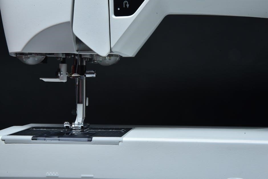
Machine Overview: Key Components
The Brother LX-3125 boasts a user-friendly design. Key components include the power switch, handwheel for manual control, stitch selection dial, stitch length and width adjustments, and the presser foot lever. Familiarize yourself with the bobbin winder, tension dial, and reverse stitch lever.
Locate the needle clamp and thread guides. Understand the function of the foot controller for speed regulation. This section provides a foundational understanding of the machine’s physical parts, preparing you for operation.
Identifying the Main Parts
Essential components include the power switch, initiating operation, and the handwheel, enabling precise manual control. The stitch selection dial allows choosing desired patterns, while stitch length/width dials customize them. The presser foot lever raises/lowers the foot, crucial for fabric handling.
Recognize the bobbin winder, tension dial, and reverse stitch lever. Locate the needle clamp, thread guides, and foot controller. Understanding these parts is fundamental for successful sewing with your Brother LX-3125.
Powering On and Off
To power on, ensure the machine is plugged into a functioning outlet and switch the power switch, typically located on the side, to the ‘ON’ position. The power indicator light will illuminate, confirming operation. Always verify the voltage compatibility before plugging in.
To power off, switch the power switch back to the ‘OFF’ position. Disconnect the power cord from the outlet when not in use or during maintenance for safety. Never force the switch; gentle pressure is sufficient.

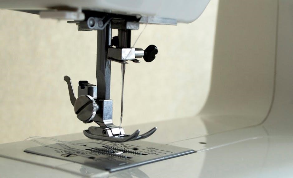
Threading the Machine
Proper threading is crucial for optimal sewing performance. This section details the upper and lower threading procedures for the Brother LX-3125. Begin by raising the presser foot; this opens the tension discs, allowing the thread to seat correctly. Follow the numbered threading path illustrated in your manual, ensuring the thread engages all guides.
Incorrect threading can lead to skipped stitches or tension issues. Refer to the diagrams carefully and re-thread if necessary. A smoothly threaded machine ensures consistent stitch quality and prevents frustrating interruptions during your sewing projects.
Upper Threading Procedure
Start with the spool pin, guiding the thread through the first thread guide. Next, lower the thread through the tension discs – remember to have the presser foot up! Continue following the numbered path, leading the thread through the take-up lever. Ensure the thread is securely seated in the take-up lever’s slot.
Finally, thread the needle from front to back. A needle threader can be helpful. Double-check that the thread is fully inserted into the needle’s eye. Proper upper threading is vital for consistent stitch formation and preventing thread breakage.
Bobbin Winding and Insertion
Begin by placing the bobbin onto the bobbin winder spindle. Engage the spindle and wind the thread from the spool onto the bobbin, ensuring even distribution. Once full, disengage and trim the thread. Now for insertion: open the bobbin cover.
Insert the bobbin into the bobbin case, guiding the thread through the tension spring. Rotate the handwheel to draw up the bobbin thread. Proper winding and insertion are crucial for balanced stitches and avoiding tangled threads during sewing operations.
Basic Sewing Operations
Mastering the fundamentals is key to successful sewing with your Brother LX-3125. Begin by understanding how to select appropriate stitch patterns for your project, utilizing the machine’s built-in options. Next, adjust stitch length and width to achieve desired results on different fabrics.
Practice starting and ending a seam securely with the reverse stitch function. Consistent tension and proper fabric handling are vital for clean, professional-looking seams. These basic operations form the foundation for all your sewing endeavors;
Selecting Stitch Patterns
The Brother LX-3125 offers a variety of stitch patterns to suit diverse sewing needs. To select a stitch, locate the stitch selection dial on the machine’s front panel. Rotate the dial to browse through the available options, referencing the stitch pattern guide for detailed explanations.
Each number corresponds to a specific stitch, including straight stitch, zigzag stitch, and decorative options. Ensure the machine is powered on to view the selected stitch on the display screen. Experiment with different stitches to discover their unique applications.
Adjusting Stitch Length and Width
Precise control over stitch length and width is crucial for achieving optimal sewing results with your Brother LX-3125. Locate the stitch length dial, typically marked with measurements, and adjust it to your desired setting. Shorter stitch lengths are ideal for delicate fabrics, while longer lengths suit heavier materials.
Similarly, the stitch width dial controls the zigzag stitch’s breadth. Experiment with different settings to achieve the desired aesthetic and functionality. Always test your settings on a scrap fabric before starting your project.
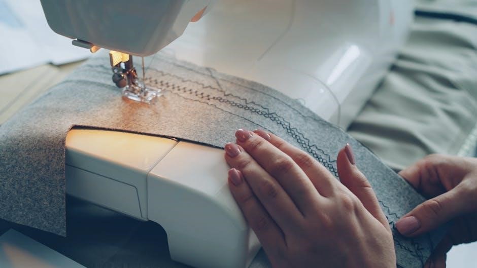
Starting and Ending a Seam
To begin a seam on your Brother LX-3125, gently hold both thread tails after threading. Lower the presser foot before starting to sew, ensuring the fabric is properly positioned under the needle. Begin sewing slowly, guiding the fabric gently.
When reaching the end of the seam, sew a few stitches beyond the desired stopping point. Use the reverse stitch function to backstitch over those final stitches, securing the seam. Raise the presser foot and carefully trim the threads, leaving a small tail.
Advanced Sewing Techniques
Expand your skills with the Brother LX-3125! Mastering techniques like utilizing the reverse stitch for secure seams is crucial. Experiment with sewing diverse fabric types – from lightweight silks to heavier denims – adjusting tension accordingly.
Explore decorative stitches for embellishment and consider using optional presser feet (sold separately) to tackle specialized projects; Consistent practice and understanding your machine’s capabilities will unlock a world of creative possibilities, enhancing your sewing expertise.
Using the Reverse Stitch
Secure your seams effectively with the Brother LX-3125’s reverse stitch function. This vital technique reinforces the beginning and end of each seam, preventing unraveling. Engage the reverse lever or button – typically located near the handwheel – before reaching your desired stitching point.
Stitch backwards for a few stitches, then release the lever and continue sewing forward. Practice achieving a neat, compact reverse stitch for professional-looking results. Consistent use ensures durable and long-lasting garment construction.
Sewing Different Fabric Types
Adapt your settings for optimal results when sewing various fabrics with your Brother LX-3125. Lightweight fabrics like chiffon require finer needles (size 60/8 or 70/10) and lower thread tension. Heavier materials, such as denim, benefit from larger needles (size 90/14 or 100/16) and increased tension.
Adjust stitch length accordingly; shorter stitches for delicate fabrics, longer for sturdy ones. Always test on a scrap piece first to ensure proper stitch formation and prevent puckering or thread breakage.
Understanding the Control Panel
The Brother LX-3125’s control panel provides intuitive access to its many features. Familiarize yourself with each button’s function – stitch selection, stitch length/width adjustment, reverse, and needle up/down. The display screen clearly shows your chosen stitch, settings, and any error messages.
Experiment with different settings to understand their impact on your sewing. Refer to the stitch pattern reference guide for detailed explanations of each stitch and its ideal applications.
Function of Each Button
Each button on the LX-3125’s control panel serves a specific purpose. The stitch selection buttons cycle through available patterns. Stitch length and width controls adjust the size and density of your stitches. The reverse button allows for backstitching to secure seams.
Needle up/down buttons position the needle for easy fabric handling. Power and start/stop buttons control machine operation. Understanding these functions unlocks the machine’s full potential for diverse sewing projects.
Display Screen Information
The LX-3125’s display screen provides crucial sewing data. It clearly shows the selected stitch pattern, stitch length, and stitch width settings. The screen also indicates the current presser foot position and any error messages that may occur during operation.
Furthermore, it displays information regarding thread tension and needle position, aiding in precise adjustments. Referencing the display ensures accurate and efficient sewing, maximizing control over your projects.
Maintenance and Troubleshooting
Regular maintenance is vital for optimal performance. Cleaning the machine removes lint and debris, preventing jams. Locate and apply oil to designated oil points for smooth operation.
Troubleshooting common issues like thread breakage or skipped stitches often involves re-threading or checking the needle. Consult the manual for specific error codes and solutions. Proper care extends the life of your Brother LX-3125.
Cleaning the Machine
Routine cleaning prevents lint and dust buildup, ensuring smooth operation of your Brother LX-3125. Power off and unplug the machine before starting. Use a soft brush to remove debris from the bobbin area and feed dogs.
A lint brush is ideal for cleaning around the needle plate. Never use compressed air, as it can force debris deeper inside. Regular cleaning maintains stitch quality and prevents mechanical issues.
Oil Points and Lubrication
Proper lubrication is crucial for the longevity of your Brother LX-3125. Locate designated oil points – typically around the bobbin area and main shaft – as indicated in the manual. Use only sewing machine oil; other lubricants can cause damage.
Apply oil sparingly with an oiler, avoiding over-saturation. Do not oil the bobbin case or feed dogs. Regular, careful lubrication ensures smooth, quiet operation and prevents wear and tear on internal components.
Common Problems and Solutions
Thread bunching? Re-thread the machine, ensuring proper tension and the presser foot is up. Skipped stitches? Check the needle – is it the correct type and size for your fabric? A bent or dull needle is a frequent culprit.
Bobbin issues? Ensure correct bobbin insertion and winding. If the machine jams, power off and carefully remove tangled threads. Consult the full manual for detailed troubleshooting steps and diagrams for your Brother LX-3125.
Needle and Presser Foot Guide
Needle selection is crucial! Use universal needles for woven fabrics, ballpoint needles for knits, and stretch needles for lycra. Needle size corresponds to fabric weight – smaller for delicate fabrics, larger for heavier ones. Regularly replace needles to prevent skipped stitches and fabric damage.
Presser feet enhance versatility. The standard foot suits most tasks, while a zipper foot simplifies zipper insertion. A buttonhole foot creates professional buttonholes, and a blind hem foot delivers invisible hems. Experiment to find the best foot for each project!
Choosing the Right Needle
Selecting the correct needle dramatically impacts stitch quality. Universal needles work well on woven fabrics, but knit fabrics demand ballpoint needles to avoid runs and snags. Stretch needles are essential for spandex and lycra, preventing puckering. Consider needle size; a smaller number suits lightweight materials, while larger numbers handle heavier fabrics.
Regular inspection is key. A bent or damaged needle causes skipped stitches and potential machine damage. Replace needles frequently, especially after sewing dense or abrasive materials. Always use needles designed for your Brother LX-3125!
Presser Foot Selection for Various Tasks
The right presser foot unlocks your Brother LX-3125’s full potential. A standard zig-zag foot handles most fabrics, while a narrow zig-zag foot excels with delicate materials and appliqué. Buttonhole feet simplify buttonhole creation, ensuring consistent results. A zipper foot allows precise stitching close to zipper teeth.
Explore specialized feet! A walking foot aids in feeding multiple layers evenly, ideal for quilting. Blind hem feet create invisible hems. Experiment to discover which foot best suits each project, enhancing both speed and quality.
Bobbin System Details
Understanding your Brother LX-3125’s bobbin system is crucial for consistent stitching. This machine utilizes a class 15 bobbin, ensuring compatibility with a wide range of thread types and weights. Proper bobbin winding is essential; ensure even distribution without overlapping layers.
Troubleshooting bobbin issues is straightforward. If experiencing skipped stitches, re-thread both the upper thread and bobbin. Check for lint buildup within the bobbin case. Always use genuine Brother bobbins for optimal performance and to avoid potential damage.
Bobbin Types and Compatibility
The Brother LX-3125 is designed to work optimally with standard, class 15 plastic bobbins. Metal bobbins are not recommended, as they can potentially damage the machine’s delicate components. Using compatible bobbins ensures smooth, even stitching and prevents thread bunching or breakage.
Always verify the bobbin’s size and shape before insertion. Incorrect bobbin types can lead to tension issues and poor stitch quality. Genuine Brother bobbins are preferred for guaranteed compatibility, but high-quality aftermarket class 15 bobbins are also acceptable.
Troubleshooting Bobbin Issues
If experiencing bobbin issues, first ensure correct winding and insertion. Uneven winding or improper placement can cause thread nests. Check for lint or thread debris within the bobbin case; clean thoroughly with a brush. Persistent problems may indicate incorrect tension.
Adjust the bobbin tension dial incrementally. If the upper thread pulls the bobbin thread to the top, loosen bobbin tension. Conversely, tighten it if the bobbin thread loops excessively. Always test adjustments on scrap fabric.
Stitch Pattern Reference Guide
The Brother LX-3125 offers a diverse range of stitch patterns for varied projects. Straight stitches are fundamental for seams, while zigzag stitches provide stretch and finish raw edges. Decorative stitches add embellishment to garments and home décor. Understanding each stitch’s application is key.
Refer to the stitch chart for detailed explanations and recommended settings. Experiment with stitch length and width to achieve desired effects on different fabric weights. Always test stitches on scrap fabric before applying to your final project.
Detailed Explanation of Each Stitch
Each stitch on the Brother LX-3125 serves a unique purpose. Straight stitches create durable seams, ideal for construction. Zigzag stitches offer flexibility, preventing fabric fraying and accommodating stretch materials. Buttonhole stitches automatically create perfectly sized openings.
Decorative stitches, like shell or floral patterns, enhance projects. The manual details stitch width, length, and tension settings for optimal results. Understanding these parameters ensures professional-looking finishes. Practice on scrap fabric to master each stitch’s characteristics.
Stitch Applications and Examples
Straight stitches are fundamental for garment construction, quilting, and basic repairs. Zigzag stitches excel in finishing raw edges, creating buttonholes, and sewing knit fabrics. Decorative stitches add flair to home décor projects like pillows and tablecloths.

Buttonhole stitches ensure secure and professional button attachments. Stretch stitches are perfect for swimwear or athletic wear. Experiment with stitch combinations to achieve unique textures and designs. The LX-3125’s versatility allows for countless creative applications.
Safety Precautions
Always disconnect the power supply before cleaning or changing the needle. Never operate the machine with damaged parts. Keep fingers away from moving components, like the needle and presser foot, during operation to prevent injury.
Do not force the fabric under the needle; let the machine feed it naturally. Ensure the machine is stable on a flat surface before use. Supervise children when near the sewing machine at all times. Proper safety practices guarantee a secure and enjoyable sewing experience.
Technical Specifications
The Brother LX-3125 is a compact and efficient sewing machine. Its approximate dimensions are designed for convenient use and storage. While specific weight details vary, it’s lightweight for portability.
Power requirements are standard for household use, typically 120V/60Hz. This machine boasts a variety of stitch patterns, catering to diverse sewing projects. It’s built with a robust motor for consistent performance and durability, offering reliable operation for years to come.
Machine Dimensions and Weight
The Brother LX-3125 is designed with user convenience in mind. Its compact dimensions allow for easy storage and portability, making it ideal for various sewing spaces. While precise measurements can vary slightly, the machine generally measures approximately 15.9 x 11.8 x 7.9 inches.
Regarding weight, the LX-3125 is relatively lightweight, typically around 13.2 pounds. This manageable weight contributes to its ease of movement and setup, ensuring a comfortable sewing experience for all users.

Power Requirements
Ensuring proper power supply is crucial for optimal performance of your Brother LX-3125. This sewing machine is designed to operate on a standard household electrical outlet. Specifically, it requires an AC 120V, 60Hz power source. Always verify your local voltage matches these specifications before plugging in the machine.
The LX-3125 has a power consumption of approximately 85 watts during operation. It’s recommended to use a surge protector to safeguard against potential power fluctuations and maintain the longevity of your sewing machine.
Accessories Included
Your Brother LX-3125 package includes a variety of accessories to enhance your sewing experience. These typically encompass several presser feet – a zigzag foot, buttonhole foot, and potentially a blind hem foot – catering to diverse projects. You’ll also find a set of needles, bobbins, a seam ripper, and a cleaning brush for maintenance.
Furthermore, a screwdriver, spool pins, and a power cord are included. A comprehensive accessory guide details each item’s specific use, maximizing the machine’s versatility and ensuring successful sewing outcomes.
Warranty Information
Brother offers a limited warranty on the LX-3125 sewing machine, safeguarding against manufacturing defects. Typically, this covers one year for parts and labor, commencing from the original purchase date. Proof of purchase is essential for any warranty claim, so retain your receipt carefully.
The warranty doesn’t cover damage resulting from misuse, accidents, or unauthorized repairs. For detailed warranty terms, conditions, and claim procedures, please consult the separate warranty card included within the product packaging or visit the official Brother website.
Contacting Brother Support
For assistance with your Brother LX-3125, several support avenues are available. You can visit the official Brother website for FAQs, troubleshooting guides, and downloadable resources. Alternatively, reach out to Brother’s customer support team via phone; numbers are listed on their website, varying by region.
Live chat support is often available for immediate assistance. Ensure you have your machine’s model number and serial number ready when contacting support to expedite the process. Brother’s website also provides access to a community forum where users share tips and solutions.